
The parts required to complete the landing gear fix finally arrived, and with them came unseasonably warm December weather. It couldn't have worked out any better! With a comfortable 50+ degrees on tap for the weekend, Pete and I decided to get as much done as possible before the inevitable cold weather returns.
I started out by marking the locations where I would be drilling 3/8" holes in the belly of the plane. These holes will provide access to four of the bolts that hold the landing gears legs onto the airplane. This access will allow for periodic inspection and re-tightening of the bolts as required.

As usual, I very precisely located the spots for the holes, knowing full well that the actually drilling of the holes will result in very imprecisely located openings. It won't matter much; there will be plenty of wiggle room for the socket extension.

With a few years of bitter experience telling me that drilling with the step bit generates lots of shavings and that gravity will ensure that mot of them fall into my eyes, I made sure to wear my safety glasses. As is typical when I do this, they only managed to block approximately ninety percent of the falling detritus. The rest will float out in tears over the next few nights.

There were eight (four per side) difficult to get at rivets to be removed down inside the center section. The only way to get at them was to climb into the plane, something I really don't like doing when it's supported only by sawhorses.

A big part of the problem that caused the release of the factory service bulletin was wrinkled side skin as a result of loose gear legs wobbling around. Unsurprisingly, a big part of the fix for the problem is hefty skin doublers. All of those circles are new holes that need to be drilled into the side skins. These doublers will improve the strength of the side skins by at least an order of magnitude, causing me to wonder just how weak this part of the design was in the first place.

Having two drills handy made it easy to get both sides done concurrently.

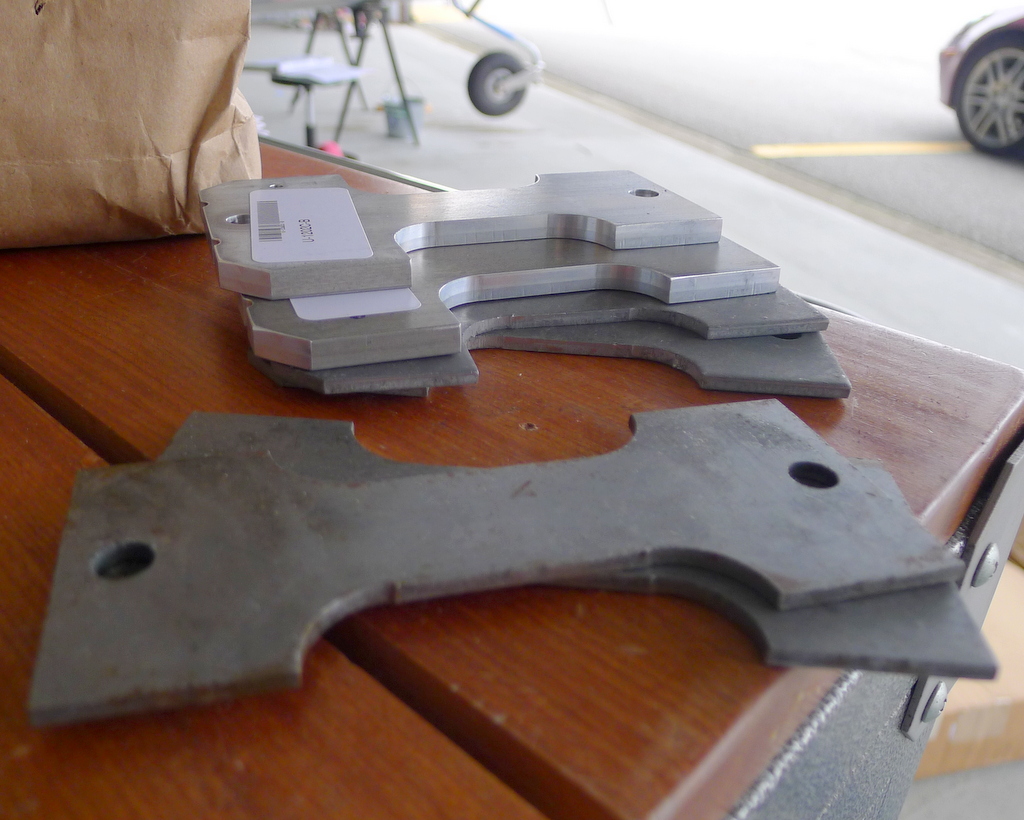
Also tagged for increased robustitude were the steel "wear plates" that formed half of the metal sandwich that held the gear legs in place. Looking at the replacement parts as compared to the original parts again made me wonder just how weak the original design was. The new parts are in the back - just look at how much thicker they are than the original parts!
As I was drilling old blind rivets out of the side of the fuselage, I couldn't help wondering what we would do to get the old rivet shop heads out of the sealed area of the fuselage. Van's suggestion was to use a 3/4" diameter piece of rubber hose attached to a shop-vac to suck the little buttons out of the enclosed areas. That worked poorly. In fact, I don't think I was able to remove a single piece of rivet. It was impossible to see inside the area in order to find the little bits. Leaving the operation to random chance by waving the tube blindly around inside the airplane didn't seem like a very good idea.

Pete came up with a better idea. He covered a finger in masking tape with the sticky side facing out and just poked around in there getting rivet bits to stick to the tape. He later improved on that plan by shaking the airplane around a little bit to encourage the rivet droppings to roll to the lower bulkhead where he could collect them in bunches.

Meanwhile, I riveted in some new, thicker side stiffeners. Access to the rivets was somewhat inconvenient.

This rivet location was particularly bothersome. The only way to reach that rivet with the puller was to follow Van's directive to tap the big brass spar bushing to push it back out of the hole in the spar. It's in there quite tightly, so I am not convinced that "tap" is the appropriate word. It took pounding to get it to move. I wasn't keen on the idea of pounding soft brass with a steel sledge hammer, though.

What we ended up doing for both moving the bushing out and pushing it back in was to use a small chunk of 2x4 to provide a soft(er) surface against the face of the bushing and a length of wood to use to pound on with the sledge. This work very, very well. Below is a picture of the setup for pushing the bushing back in.

Even with the bushing out of the way, the rivet puller was at a slight angle when trying to pull the rivet. These are not the normal blind rivets used in the rest of the plane - these are special rivets known as "cherry rivets." They are much stronger than the regular rivets used just about everywhere else on the RV-12, and something about that makes them impossible to pull at an angle without the mandrel immediately breaking off. When this happened, it left the remainder of the rivet in the hole with no way to complete the pulling. I was at a loss as to what to do about this, but after thinking it over, I decided to treat is as if it was a solid rivet. In other words, I just drove it in with a rivet gun and a bucking bar. The little brass thingy is a little extension we made out of brass plumbing parts from the hardware store. The cherry rivet actually isn't a solid rivet, so I used very light sir pressure and only a few taps from the rivet gun to finish its set. Looking at the shop head once I had finished tapping it, it was impossible to tell that it had been done any differently than they ones I set with the rivet puller.
NOTE: There are those that believe that it makes a difference from which direction the shop head of the rivet is formed, so use your own discretion. I can't see what possible difference it could make and I am perfectly comfortable with my decision, especially when considering the relative weakness of Van's original design that used a normal LP4-3 rivet in this exact same hole, but seriously, do what you think is right. I'm just here to share my experiences, not to tell you how to build your airplane. It is becoming abundantly clear to me why Dan Checkoway deleted his entire RV-7 build blog, though.

Once that was done, it was a simple matter to rivet in the side doublers. Well, it would have been simple if the cherry rivets didn't display a propensity to jam up the Harbor Freight pneumatic puller. The first time it happened, I took the puller over to the work bench to disassemble it in order to figure out why it had jammed. That in itself wouldn't have been a problem, but I have somehow developed the bad habit of absent-mindedly carrying stuff with me and leaving it sit somewhere else, only to return to the work site to find something mysteriously missing. In this case it was the small plastic bag of cherry rivets. Nowhere to be seen. And quite the mystery it was, too. I retraced my steps, but they were nowhere to be found.

Having a far superior institutional memory than I do, Pete remembered the lesson that we learned after finding a dropped part in the most unlikely location (it had fallen into the open bottom of one of the control sticks), that lesson being that odds are that if we can't find something easily, it has found its way into the very last place you would expect it.
And so it was. We found the bag of rivets.

As usual, the actual riveting was really a bit of an anti-climatic event once we figured out how to easily un-jam the rivet puller.

Edit: I was just planning to use one of the standard 100 deg 1/2" piloted bits in the spindle portion of a disassembled countersink cage.
The bit I ordered is too narrow. I'm going to try the suggestion above if the bits I happen to have on hand are wide enough.
There are also four 1/4" holes to be drilled all the way down through the center section and those big mounting plates. As long as I was ordering the countersink, I ordered a nice 1/4" bit.
We're on hold until those arrive. Hopefully they will end up being the right tools for the job.
3 comments:
The rivet for the side stiffner near the spar bushing can be installed from the bottom
Thanks for documenting your work including mishaps as selflessly as usual, Dave. I am about to start the SB ans will certainly have your posting at hand.
Thank you for sharing this. :)
Best,
Thomas
Post a Comment