
"The what?" you ask? Well, to put it simply....
A pitot (/ˈpiːtoʊ/) tube is a pressure measurement instrument used to measure fluid flow velocity. The pitot tube was invented by the French engineer Henri Pitot in the early 18th century and was modified to its modern form in the mid-19th century by French scientist Henry Darcy. It is widely used to determine the airspeed of an aircraft and to measure air and gas velocities in industrial applications. The pitot tube is used to measure the local velocity at a given point in the flow stream and not the average velocity in the pipe or conduit.
The basic pitot tube consists of a tube pointing directly into the fluid flow. As this tube contains fluid, a pressure can be measured; the moving fluid is brought to rest (stagnates) as there is no outlet to allow flow to continue. This pressure is the stagnation pressure of the fluid, also known as the total pressure or (particularly in aviation) the pitot pressure.
Meh, those people get paid by the word (with bonuses paid for using quad-syllable or more words). To put it more simply, the pitot tube collects the air that is used to drive the speedometer.Theory of operation
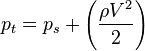
The measured stagnation pressure cannot of itself be used to determine the fluid velocity (airspeed in aviation). However, Bernoulli's equation states:
- Stagnation pressure = static pressure + dynamic pressure
Which can also be written
- V is fluid velocity;
- pt is stagnation or total pressure;
- ps is static pressure;
- and ρ is fluid density.
The value for the pressure drop p2 – p1 or Δp due to Δh, the reading on the manometer:
- Δp = ρ g Δh
Where:
- ρ is the density of the fluid in the manometer
- Δh is the manometer reading
The dynamic pressure, then, is the difference between the stagnation pressure and the static pressure. The static pressure is generally measured using the static ports on the side of the fuselage. The dynamic pressure is then determined using a diaphragm inside an enclosed container. If the air on one side of the diaphragm is at the static pressure, and the other at the stagnation pressure, then the deflection of the diaphragm is proportional to the dynamic pressure, which can then be used to determine the indicated airspeed of the aircraft. The diaphragm arrangement is typically contained within the airspeed indicator, which converts the dynamic pressure to an airspeed reading by means of mechanical levers.

I've mentioned the changes from traditional configurations that were made in the RV-12 to provide for the removable wings, and the location of the pitot tube is yet another of those. Most small planes have the pitot tube under one of the wings. Having the pitot on the RV-12 wing would require a fitting at the wing root to allow for the connection and disconnection of the air tube that runs from the pitot to the airspeed indicator, or in the case of the RV-12, the air data computer. That would be just one more thing to forget when re-attching the wings, so Van's moved the pitot tube to a rather exotic location: it protrudes from the very front tip of the propeller spinner. This is somewhat similar to the cannon mounted in the WWII P-39 Airacobra.
The net effect for the builder is that the installation of the pitot is a PITA.
It's definition #1 that best fits the occasion.
The first step was the preparation of the tube. Van's provides a somewhat convoluted procedure involving masking tape, a collection of washers, and a few paragraphs of obfuscatory text to keep things interesting. The end result is a dimple that will assist a locking screw in the critical job pf keeping the pitot tube attached to the airplane and correctly oriented to the preferred airflow direction.

When drilling this hole, it is strongly preferred that the hole, which is not really a hole per se, not become an actual hole. Rather, the idea is to drill it just deep enough that a small bump becomes visible inside the tube. For this job, I chose the eminently controllable hand drill that worked so very well when drilling the delicate canopy glass.

I paused after every few twists to take a look to see if the bump was showing yet. As it turned out, Pete saw it first. It really looked just like a piece of dirt that had gotten into the tube. It was a small bump indeed.

I found out later that it was actually on the wrong side of the tube, so we got to do this part twice.
Then we installed the plastic-ish block that holds the tube. This is where the PITA-factor came in. First, the plans referred to the "threaded" side of the block, but I was unable to find any threads. The tube fit tightly enough that I think it tapped some threads on the way in, though. The bottom aft edge of the block also had to be chamfered a little bit to give clearance from the cooling shroud. This would be the least of the difficulties with the shroud. Do you see the bolt that's only partially screwed in? That would be because the cooling shroud obstructed any kind of tool from working on the bolt.

I tried using fingers, but it put up too much resistance.

I enlisted the aid of pliers.

Getting the thing tightened was difficult. Getting it safety wired was even more so.

The pitot line had to be attached to the pitot tube using a small length of plastic, cleverly sized by the engineers at Van's to be precisely one nanometer too small. It took one of Pete's innovative ideas (using an open end wrench to fork over the smaller pitot tube and put pressure against the larger tube with the sides of the wrench "fork") to get the tubes installed. That was difficult, but again it was the safety wiring that was worse.

All in all, this took almost three hours out in the cold, after which I had no appetite for the cutting/fitting work that will have to be done on the spinner before the propeller can be installed. I've given up on trying to guess when that will be.
4 comments:
You just installed a nice sharp spear on the front of your plane. A place where you will be working a lot for the rest of the build. A place easy to bump and bend that thing. Be careful! I am putting the pitot in as one of the last things. The block is in but your pics show that the pitot attachment and safety wiring (nice job BTW) will not be easy. Bill_H
Bill -
You're absolutely right. There's no picture of it, but there is a bright blue, foot long piece of 3" masking tape dangling from the pitot, and a trash can sitting underneath it to force me to walk around it rather than try to walk through it. The prop and spinner go on next, so this is a short-term problem.
I forget - have you finished fitting the cowlings? You have to take them on and off a few dozen times and the prop gets in the way - because for one person you stand right in front of the plane to do it. You only need the backer plate of the prop mounted to check the cowling clearances. Bill H.
Dave, did you actually use the asked for #29 bit? I don't have one and wonder if a #30 bit would do just as well....
Post a Comment